Stylized Linear Gradients
AuthorAlessa "Codekitten" Baker Page StatusComplete Unreal Version4.0+
This article was originally written for 80.lvl, thank you for hosting my little tutorial!
This tutorial is to teach you the basics of creating that stylized linear gradient seen in games like DOTA and League of Legends. We’ll be focusing mostly on learning World Position, Object Position and Object Radius. These three nodes combined will allow us to achieve the effect we need.
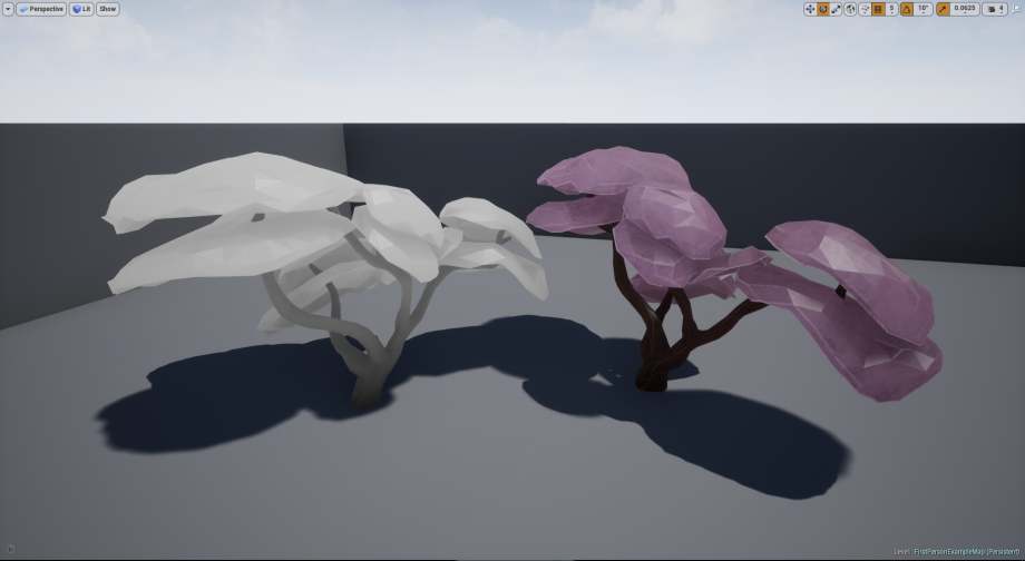
In this tutorial I’ll be using a stylized blossom tree created by the awesome Jonathan Riley and has donated it to be used with this tutorial. All files for this tutorial will be available by the download link at the bottom.
So let’s get started!
Absolute World Position
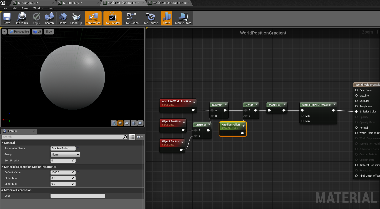
So, first things first – Let’s talk Absolute World Position. This material editor node gives the exact X, Y, and Z coordinates of your material on an object, relative to world. To demonstrate this, let’s create a basic material, I’m calling mine M_Stylized (which will become the basis for all stylized assets we use) and let’s drop in a ‘World Position’ node and plug it into Emissive.
Placing this on our mesh you’ll see a glowing sphere of different colors, each color represents a different Unreal Unit at a given point per axis (X, Y, Z). To make this more visible, let’s place a clamp right after it and plug it into emissive.

World Position Node in Emissive
By placing this material on any mesh in our scene and moving it around, you’ll find the color of the material changing based on the colors of its position.
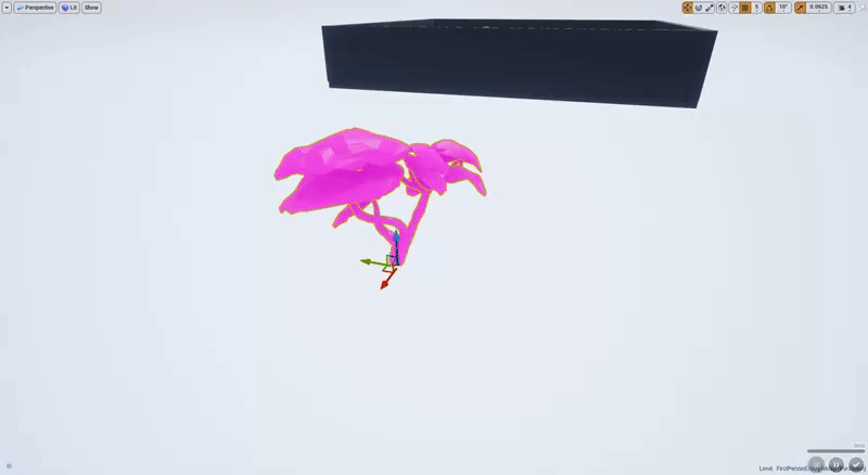
Absolute World Position on a mesh
Relative Positioning
So naturally, for our linear gradient we need to grab the Z vector, as we want our gradient to face upward in our material. Let’s add a component mask before the clamp and use B (Z), unchecking R and G. Once we place this on the mesh, drag the mesh around and you’ll find that when the mesh passes below the grid in editor, Z: 0.0, the mesh will turn black.
Gradient split relative to world
However, we would like our gradient to stay relative to the mesh itself. This means we’ve got some math to do! This is where Object Position and Object Radius come in. Object Position gives us the value of the center point of the bounds the material is assigned to. We’ll subtract this from our World Position Now you’ll find a hard split of black and white that stays with our mesh when we move it up and down! This will become the basis of our gradient.
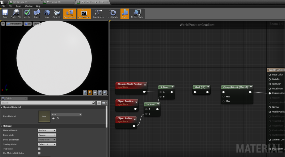
Subtracting our Object Position and radius to keep things relative.

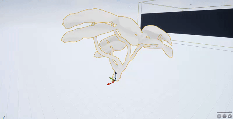
An example of our gradient moving relative to the object.
Relative Scale
Let’s bring Object Radius into the mix. Object Radius gives us a value equal to the overall radius of our object. We will subtract this from our object position, you can think of this as a ‘range’ between bounds and center of the mesh.
Again, we want to make sure our math is subtracted from the world position.
When we do this, you’ll find the mesh is white, this is because we’re not taking into account the height extent we want our gradient to travel up. We can do this by dividing by a scalar value before our component mask. Changing this value extends or decreases the falloff on our gradient.
Giving our gradient an exponent.
As an example, I’ve created a material instance and made the scalar value a parameter to show below.
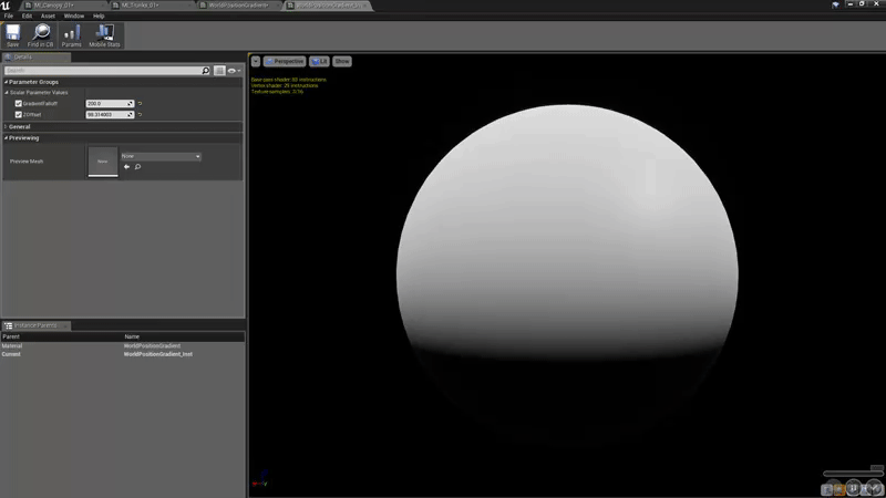
An example of how the parameters work in a Material Instance.
Position Offset
Alright! So we now have a very cool looking gradient that we can use for our stylized characters and props. But let’s say you want the gradient to begin higher up on the mesh instead of at the bottom? Well we know that the Object Position, that gives us the center of the bounds to our object, subtracting the object radius giving us our radius value for the gradient. We also know that these values give us a Vector 3, or X Y and Z coordinate.
So why not offset the Z by adding to it? Let’s give it a shot. To create our new vector, we’ll take a Vector 2 and append on a scalar parameter. This gives us a new vector where X and Y are constant at 0, and the Z is our variable.
If we add this to our math to find the gradient, we retain our X and Y, because adding 0 gives you the same value, and adding the Z’s together gives us our offset for where the gradient starts.
And here is an example of it in action!
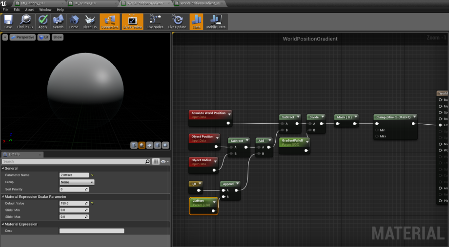
Adding ZOffset to our position.
Final Touches
Now we have a 0-1 gradient value that we can plug into a Linear Interpolate node. This node blends between two inputs based on an alpha, in this case our gradient. For the purposes of the tutorial, rather than using two different albedo textures, I’ve just multiplied one by 0.1 to get a much darker version of the same texture. By plugging the multiplied one into A, and the original into B, we get a gradient between light and dark. Here is an image of the final material.
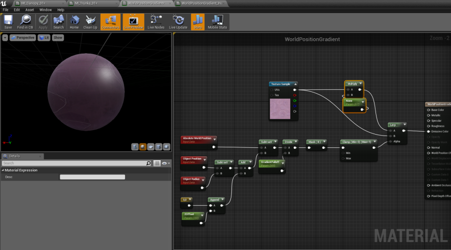
Linear interpolating diffuse color by gradient.
Let’s apply this material to our mesh and see what our results are.
Final Stylized Linear Gradient, isn't it pretty 🥺❤️
If you have any questions, feel free to email alessa@codekitten.me – I’ll be happy to answer.
Alessa ❤️
Additional Resources
[1] Original Article on 80.lvl 80.lv